Pergola Wind Load Calculation: EN 1991-1-4 for Bioclimatic Aluminium Systems.
A bioclimatic pergola is not garden furniture — it is an outdoor structure with quantifiable loads. Anyone installing or specifying a louvre roof system in Europe must understand wind load calculation
A bioclimatic pergola is not garden furniture — it is an outdoor structure with quantifiable loads. Anyone installing or specifying a louvre roof system in Europe must understand wind load calculation to EN 1991-1-4 and what a compliant system must demonstrate. This guide covers the calculation basis, European wind zones, and what a norm-compliant pergola system must document.
---
Why EN 1991 applies
Eurocode EN 1991 "Actions on Structures" has been mandatory across Europe since 2013 for permanent structures. Part 1-4 governs wind actions. Bioclimatic pergolas, as permanently installed load-bearing structures, fall within its scope — regardless of whether they require planning permission.
The manufacturer of a pergola system must demonstrate that its structure withstands the wind loads of the relevant wind zone. Without that demonstration, liability for damage passes to the installer.
---
European wind zones
Each European country uses EN 1991-1-4 with a national annex that defines basic wind velocity by zone. For Germany:
| Wind Zone | Basic Wind Velocity | Typical Regions | |---|---|---| | WZ 1 | 22.5 m/s | Parts of Bavaria, Baden-Württemberg, Saxony (inland) | | WZ 2 | 25.0 m/s | Most of Germany (mid-altitude regions) | | WZ 3 | 27.5 m/s | North German Plain, coastal proximity | | WZ 4 | 30.0 m/s | North Sea coast, islands, elevations above 800 m |
The Netherlands and Belgium have comparable zoning under their national annexes; the UK uses wind speed maps under BS EN 1991-1-4.
---
Calculation steps
Step 1: Peak velocity pressure
The peak velocity pressure qp(z) depends on the wind zone, terrain category, and height above ground. For a freestanding pergola at 3 m installation height in terrain category II (open terrain), qp ≈ 0.60–0.70 kN/m² applies in WZ 2.
Step 2: Force coefficients
For free-standing canopies (EN 1991-1-4 Annex B), force coefficients cf depend on roof pitch, louvre closure state, and geometry. A louvre roof in the closed position behaves as a solid canopy (cf ≈ 1.3–1.8 depending on exposure).
Step 3: Total wind force
Fw = cf · qp(z) · Aref
For a 4 × 5 m pergola (20 m² roof area) in WZ 3 with cf = 1.5, the governing horizontal wind force is approximately 14.4 kN on the complete system.
Step 4: Foundation anchors and post connections
The calculated wind force is distributed to post connections and foundation anchors. With four posts and a bending moment of approximately 3.6 kN per post, the anchor and base plate must be rated accordingly.
---
Open vs. closed louvre position
The wind load profile of a bioclimatic pergola changes fundamentally with louvre angle.
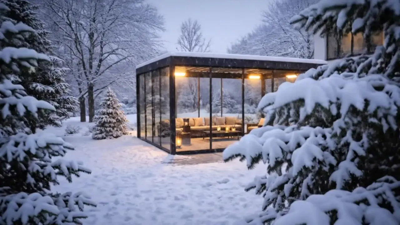
Louvres closed (0°): The roof acts as a solid surface. Wind loads strike the full roof projection. This is the governing load case for structural design.
Louvres open (90°): Louvres stand vertical; wind passes largely through. Effective wind load reduces to approximately 20–30% of the maximum value.
Storm recommendation: Manufacturers recommend opening louvres above 80 km/h wind speeds to reduce the wind attack profile. Motorised systems with wind sensors (Luxa 700 with optional anemometer) can automate this.
---
Snow load: EN 1991-1-3
In parallel with wind load, snow load to EN 1991-1-3 must be considered for pergolas in snowfall-prone locations. Characteristic ground snow loads range from 0.65 kN/m² in lower zones to 3.0 kN/m² in Alpine regions.
For louvre roofs with drainage: with louvres fully open, snow cannot accumulate. With louvres closed, the full snow load value applies.
---
What a compliant system must document
1. Structural calculation — prepared by a qualified structural engineer, covering wind and snow load for the maximum applicable zones 2. Technical data sheet — profile cross-sections, wall thicknesses, alloy and temper 3. Installation drawing — anchor type, embedment depth, torque values 4. CE Declaration of Conformity — where the system falls within EN 1090 scope
PONARC systems (PONARC) are supplied with structural documentation for wind zones 1–3. Zone 4 and special locations (Alps, exposed ridges) require a site-specific calculation.
---
*Structural documentation for PONARC systems is available through authorised PONARC dealers: ponarc.com/en/planning*
PONARC project note
For Pergola Wind Load Calculation: EN 1991-1-4 for Bioclimatic Aluminium Systems, the useful specification route is to connect the idea to the real opening, substrate, exposure and intended use. PONARC treats the page as a decision aid: which system family fits, what must be checked, and which assumptions should stay project-specific rather than generic.
Next step
Send the relevant dimensions, photos of the installation area, location context, preferred finish and use case. PONARC can then map the request to the correct product family, technical checks and quotation path without adding unsupported performance claims.
PONARC PROJECT NOTE
How to use this article in a real specification
Treat the article as a planning filter, then confirm dimensions, exposure, fixing surface, operation route and documentation needs with the PONARC team before final quotation.
- Shortlist the matching product family
- Check site assumptions before comparing prices
- Send a brief or drawings for project review
Interested in PONARC products?